How to use the timing gauge tool on an ignition for AM6 and Derbi?
Disassembling the original ignition
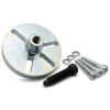
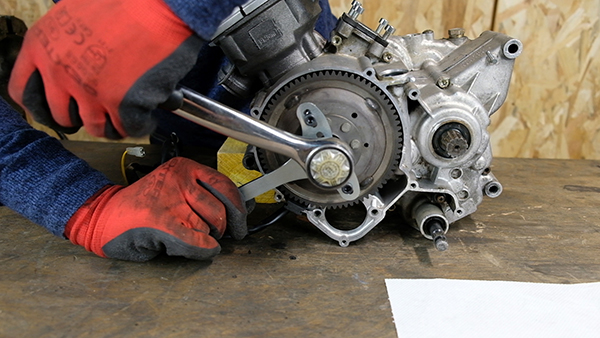
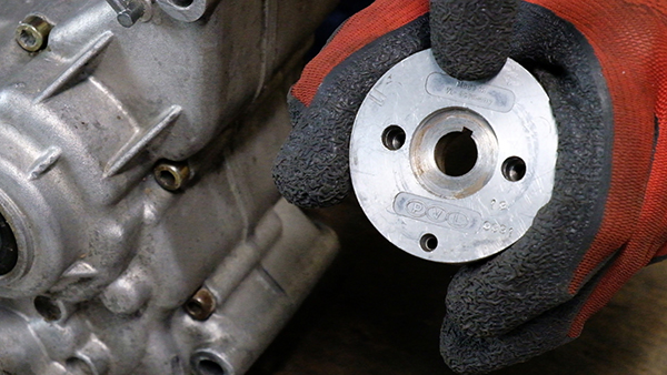
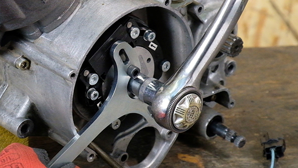
With the help of the Easyboost rotor locking tool, we will be able to lock the original ignition rotor in order to loosen the nut with a ratchet and a 13 mm socket (can be changed according to the nuts).
Removing the ignition rotor
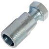
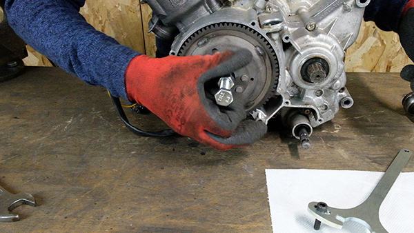
Using the AM6 / Derbi flywheel puller, we can easily remove the ignition rotor. If you are performing the operation on an engine already equipped with an internal rotor ignition, you will have to use the Easyboost Universal Puller.
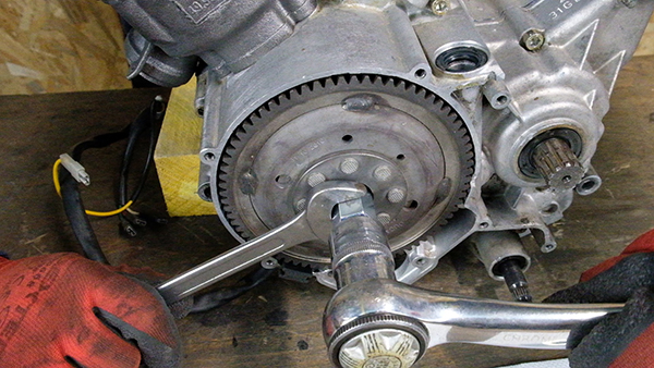
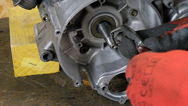
The ignition stator must now be removed by tightening the main bolt of the puller with a ratchet, while holding the fixed part of the puller with a 17 mm spanner.
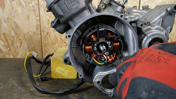
The rotor comes out easily, it only remains to remove the stator by unscrewing the 3 fixing screws of the plate.
Installation of the internal rotor ignition type PVL
An ignition consists of a plate, the stator, the ignition rotor, a CDI and a coil. We will install the ignition stator using the supplied mounting plate. The connections are easy to make, everything is detailed in each manual. Some ignition rotors are equipped with a slot for the key, as you can see below. In this case, simply place the ignition rotor on the crankshaft with the key.
For the purpose of this tutorial, we will assume that you do not have a slot for the key on the rotor. You will have to remove the key from the crankshaft.
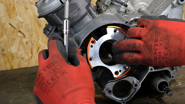
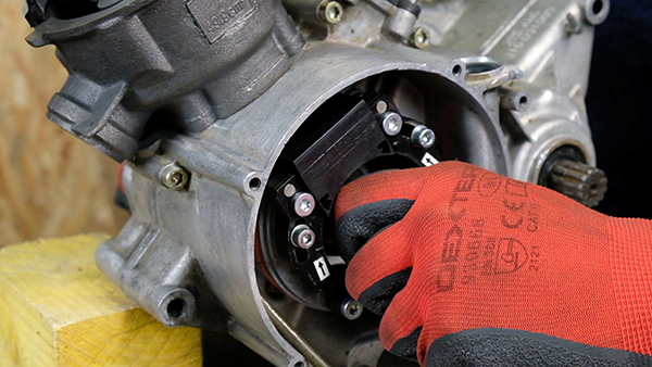
Installation of the stator
First of all, the ignition plate has to be installed with the 3 original screws (or those delivered with the ignition).
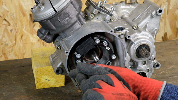
... and the ignition stator.
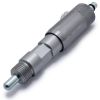
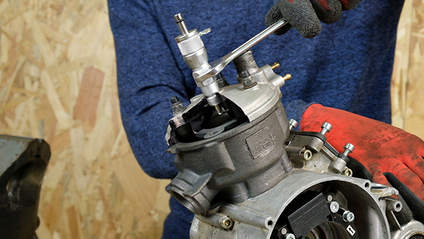
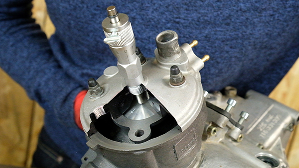
Installing the Easyboost timing gauge tool
First of all, you have to put the timing gauge tool in place of the spark plug, then tighten the body of the tool with a 17 mm spanner.
Now you have to find the top dead centre (TDC). To do this, simply loosen the head of the tool by about 3 or 4 turns.
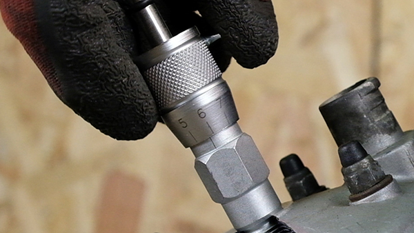
Next we will align the "0" mark on the head of the tool with the single mark on the body of the tool.
Then loosen the violin screw so that the rod slides freely and arrives at the lowest point.
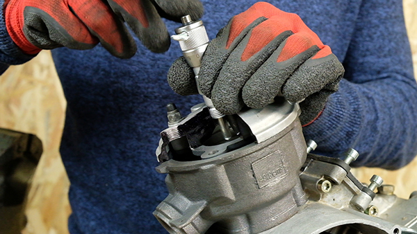
Then we have to tighten the violin screw so that the rod slides with effort. We will then turn the crankshaft so that the piston comes into contact with the rod and indicates the top dead centre (TDC).
Setting the ignition according to the value given in the manual
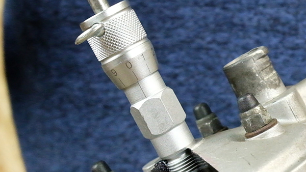
For this step, you have to consult the instruction manual of your ignition and note the recommended setting value. On the ignition used for this tutorial, the manufacturer indicates to set the ignition at 3,2mm before the top dead centre (TDC). Of course, this setting value will depend on the ignition you have. Then, tighten the fiddle screw to the maximum in order to block the rod. We are now going to lower the Easyboost tool by 3.2mm. You must therefore turn the head of the Easyboost tool by 3 turns + 2 graduations. As a reminder, 1 graduation = 0.1mm.
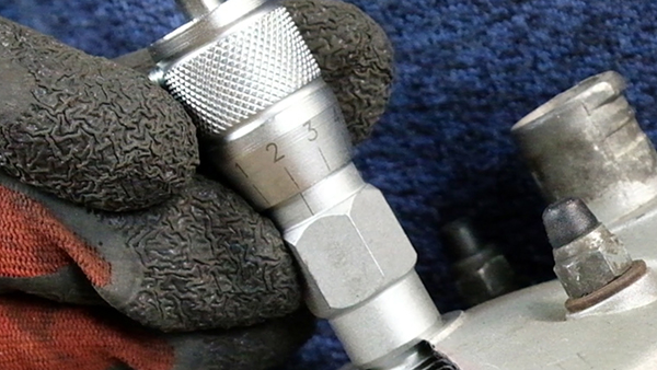
The 2 marks are well aligned and the rod is now lowered by 3.2mm. Now turn the crankshaft counterclockwise until the piston comes to rest against the rod. Thanks to the Easyboost timing tool, the piston is now 3.2mm before top dead centre (TDC).
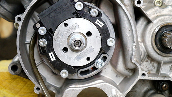
Installation of the PVL ignition rotor and alignment of the markings
The next step is to install the ignition rotor. The single rotor mark must be aligned with the rotor mark. To know which mark to use, take the arrow that indicates the direction of rotation of the engine. In the case of an AM6 or Derbi type 50 motorbike engine, when you are on the ignition side, the engine turns counter-clockwise. In our case, we must therefore take the mark with the arrow that turns counter-clockwise.
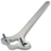
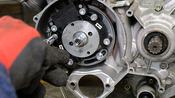
The ignition nut must then be tightened using the Easyboost universal rotor locking spanner, which is also designed for all internal rotor ignitions on the market.
In order to fine-tune the setting, it is necessary to repeat the ignition timing operation and then adjust the stator using the 3 screws that hold it to the plate. This will allow to obtain a precise setting and thus obtain the maximum performances.
VIDEO TUTORIAL
To go further, here is the video tutorial of the adjustment an internal rotor ignition on an AM6 engine (same procedure on Derbi):